3DEXPERIENCE Additive Manufacturing Engineer (A3D) Role and FFF Supports
I'm a GoEngineer SOLIDWORKS and CAM specialist, but have extensive experience in Additive Manufacturing (hence my fun with the CATIA LTX role last week). I decided to spend my morning in the 3DEXPERIENCE Additive Manufacturing Engineer (A3D) role. I created a cell for the recently announced Bambu Lab X1E 3DPrinter and prepared a replacement part I designed for my phone charger.
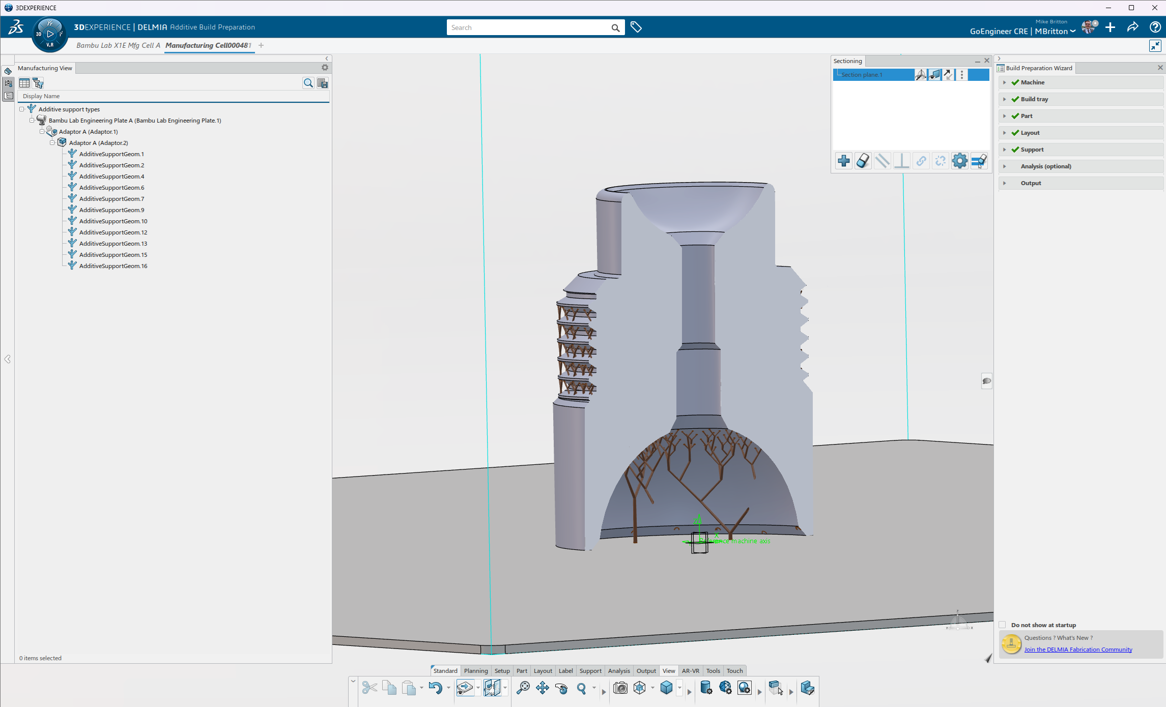
The 3DX DELMIA A3D role brings professional CAM tools to AM. Here we can set up a manufacturing cell, build plate, rules, etc. The current greatest value-add, however, is parametric control over support structures:

This is the support editing interface. There are also direct editing (click-and-drag) methods of support editing as well.
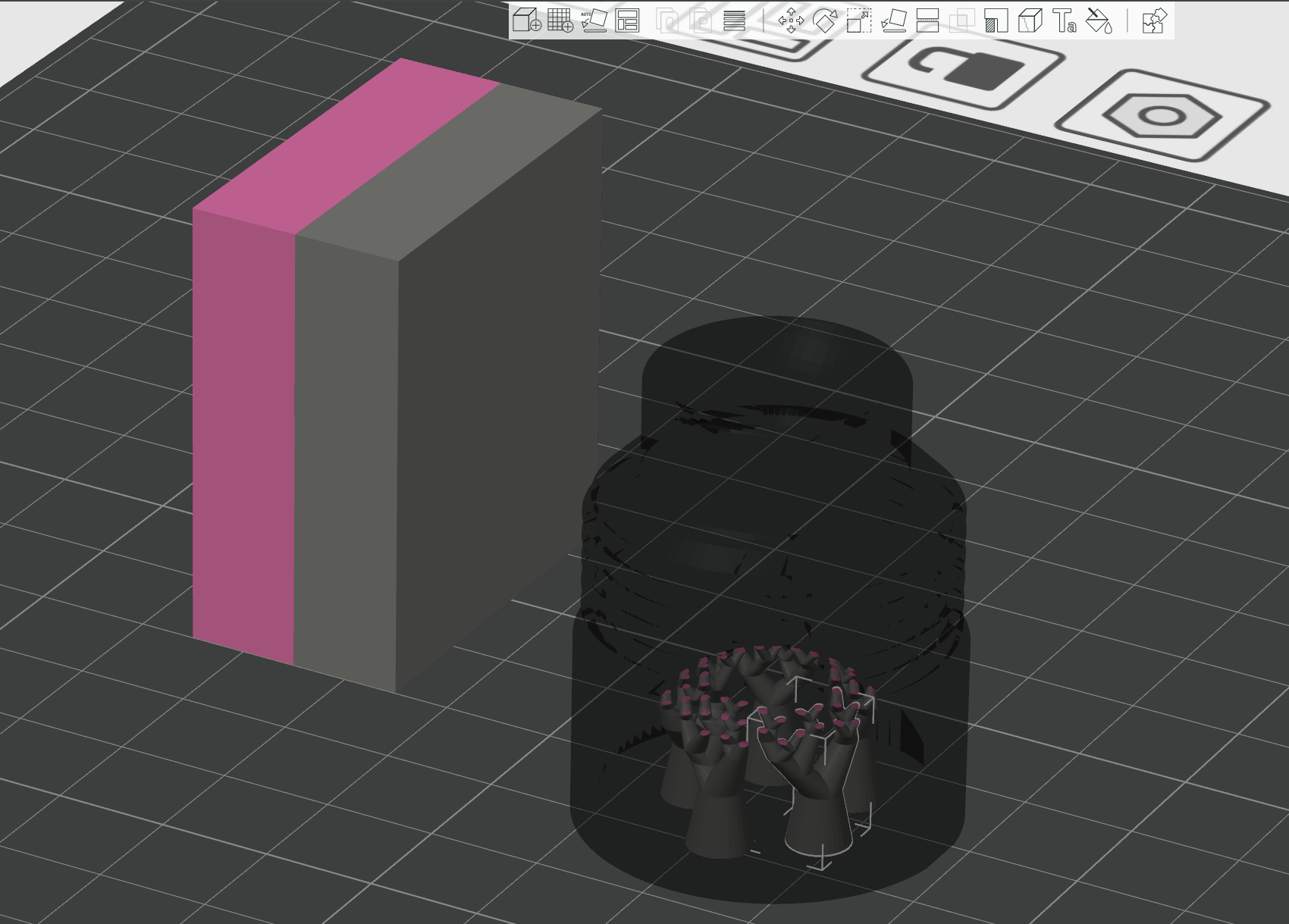
I wanted to create these structures in A3D, keep the majority of the structure in model material, and set only the interface layers to my support material in Bambu Studio.
IT WORKED!

In CAM, minimizing tool changes is the number one way to reduce cycle times (and time is money!). Since this printer has only one toolhead for multiple materials, this means that there are TWO time-consuming filament-purges and temperature adjustments per material change.
This is a category of problem -- even on multi-toolhead machines, printing an additional body of a separate material introduces compounding acceleration and print head moves on every layer. These contribute to higher cycle times.
Additionally, support materials are usually an industry-specific set of soluble or low-bonding thermoplastics which require a long time to dissolve, or expensive solvents to remove. Both the support materials *and* their solvents can dramatically contribute to the cost of individual parts, as they are more costly than model material. This is one reason why powder-bed and resin-based solutions are so popular -- you can achieve geometry that would otherwise be too costly on Fused Filament Fabrication (FFF) processes.
So what are the advantages here? First, cost reduction for cycle times, materials, and post-processing.
The next advantage comes from the fact that operators are able to create, test, and save rules for their support generation. The usual solutions around support materials either:
1) Generate supports in model material - this means that the supports are *extremely* well bonded to your model part, and removal is tedious and can negatively impact surface finish. Breakway supports have been improving over the last year or so, but there can still be drooping, and most slicers only offer primitives (prismatic geometry) to enforce or block supports on model geometry.
2) Entomb models in support material - this means that extracting a part from support material requires a lot of time spent post processing, frequent interaction with chemicals, and a lot of manual labor.
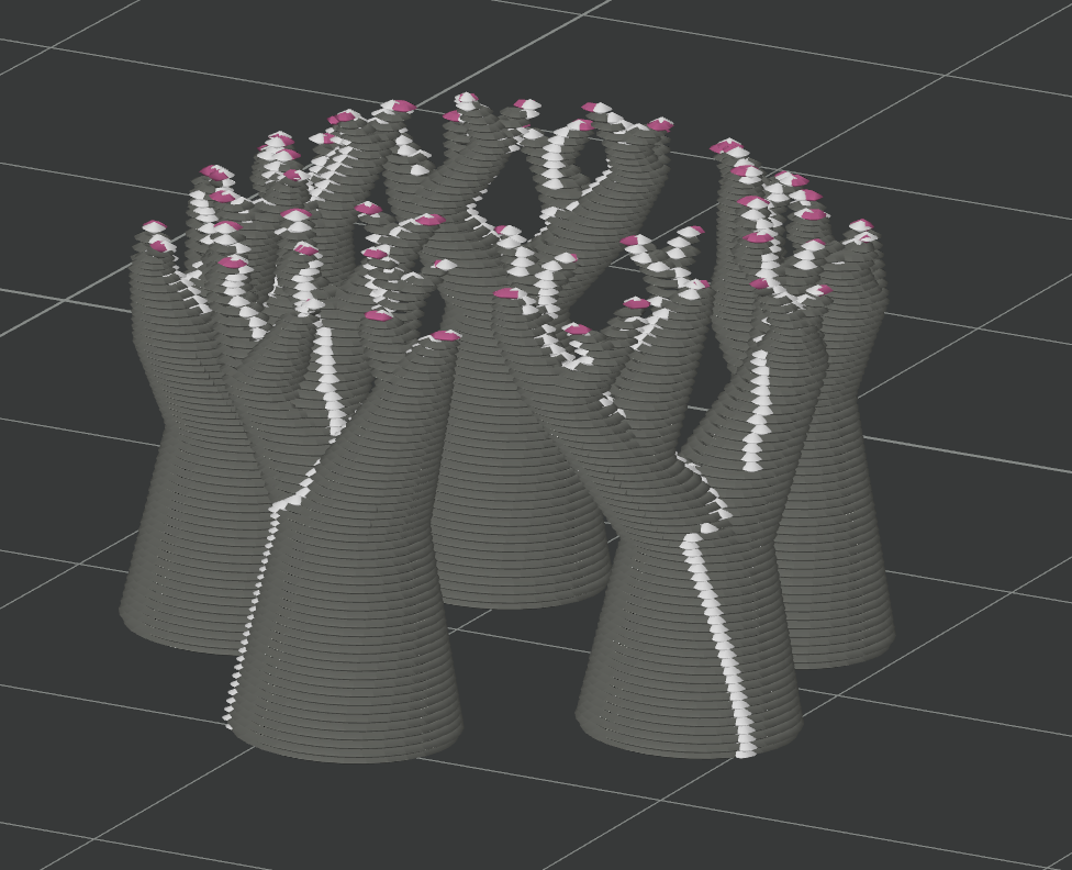
Here, we get the best of both worlds. Minimal cost on support material by setting *only* interface layers to change materials and minimal time in post-processing because only a tiny amount of support material has to be dissolved from the model.
This is one of the roles I'm truly ecstatic about in the SOLIDWORKS channel, and the benefits are enormous. How did they fare on this test?

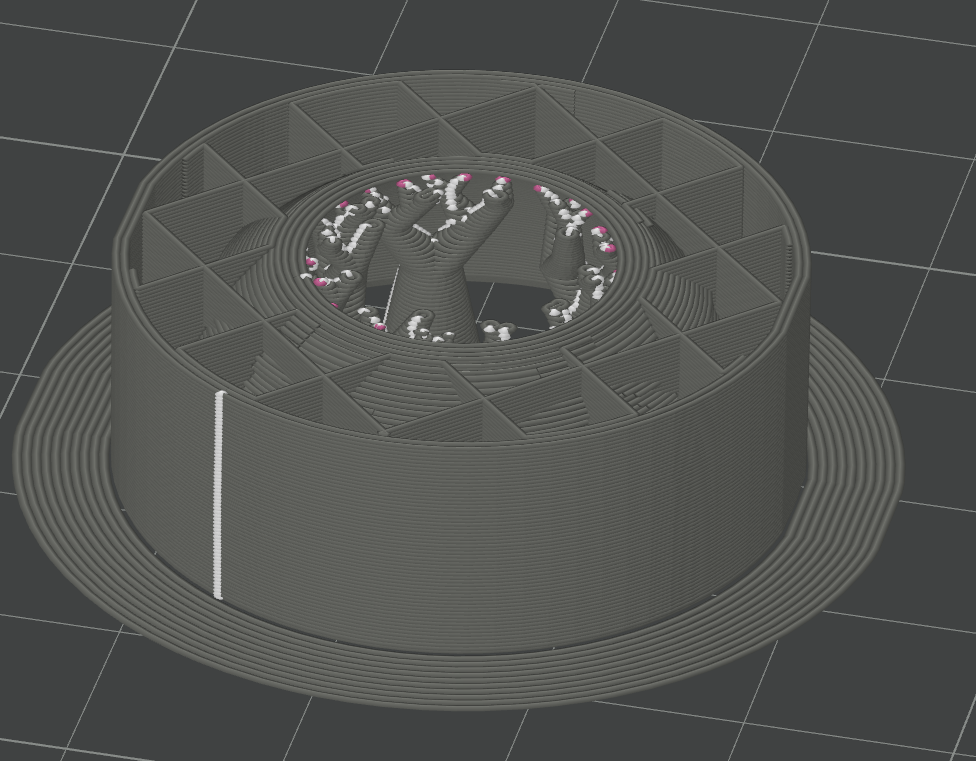
By being mindful of this simple part design, we can see that editing the interface layers reduced the cost of this one print job by 27% and the total time to print by nearly 50%! If we ignore the preparation time for the printer, we go from taking less than an hour to 2 hours, 18 minutes. The total amount of material used is also reduced by 40% because of the reduced number of filament changes.
I think this primarily represents a lower bound, the best-case scenario for this kind of addition, but it shows how many gains can be made here. Is a single layer of interface material sufficient? Time will tell, but we’ve moved from having to immerse a part in a bath for hours to dissolve material to simply wiping it away with our solvent of choice.
I can’t wait to try this out for several other machines and machine types — if we can unlock these kinds of gains in a few simple steps for FFF printers, what can we achieve with our other processes?