PS1: How to Succeed Using Preform for the Form 3 SLA 3D Printer
This article was originally published as a guide for Pumping Station: One in Chicago on February 17th, 2022. I have shared this guide with many institutions ranging from other makerspaces to users at Lawrence Livermore National Laboratory. We provided Tough 1500 and Clear resins to our members for the printed parts service bureau on this machine.
Introduction:
This is an informational post for folks who either need a refresher or would like to learn more about SLA style 3D printing. Many of the fundamentals are the same as FDM/FFF (Fused Deposition Modeling/Fused Filament Fabrication) printing like you do on the Enders/Prusas, such as the placement of supports, but there are other considerations involved due to the nature of the manufacturing process.
Preform is the free slicing software for the Form series of 3D printers. It is available for both Windows andmacOS. You can prepare your prints at home either for authorized use with personal resin & trays or to prepare your part for the PS1 Paid Parts Service.
How SLA Printing Works
SLA (stands for Stereolithography) is “upside down” from FDM printing. A build plate is dipped into a tray of resin and a laser selectively cures the resin in position. Unlike FDM printers, though, SLA prints are watertight and isotropic. Formlabs have a fantastic guide located here to help you better understand the fundamentals of SLA 3D printing.
Form 3 or Prusas/Enders?
There are a variety of tradeoffs - frequently FDM printers can give you more mechanically sound parts, but SLA prints are substantially more detailed and have superior surface finish - additionally you can achieve geometry that often isn’t possible with FDM printers. The Pumping Station: One Paid Parts Program for the Form 3 printer specifically uses both Clear and Tough 1500 resins because of the unique properties of SLA printing and these materials. You can polish Clear parts to be optically clear and Tough 1500 parts are compliant, durable, and can be machined for use in special fixturing.
For 90% of jobs, the automatic job preparation settings in Preform are going to work for you.
How to Prepare a Job for the Form 3
If your model requires manual adjustments, the first step is to read this document.
It is made by Formlabs to help you print correctly. It explains why tilting your model is important and how to reduce suction forces against the plastic sheet at the bottom of the tray. If the suction forces are too great, your part will get stuck to the tray pulling that area off your print causing it to fail.
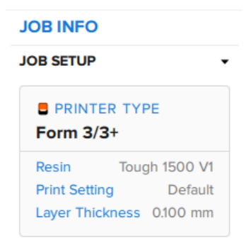
Job Setup
When you launch Preform and import a model, it will look something like this:

The model within is a yo-yo downloaded from GrabCAD. Be sure that when setting up your prints that you are choosing the correct printer and resin. The printer we have is the Form 3 printer. If you are using the paid parts program, make sure you have selected the correct type of resin. You can see both parts on the right hand side.
Model Orientation
You’ll need to orient your model with the information from the above article in mind - going for the smallest cross-section you can while reducing islands. You’re welcome to automatically or manually orient your models. If manually tilting, you get more control to make sure that your supports are mostly generated on the side that will not be seen in its final application.
In the yo-yo example, I have tilted the model about one axis to minimize the cross-section and to put an embossed area on the top, away from where supports will go, but you can see that I get a warning for suction cups, illustrated by the yellow area on the model:
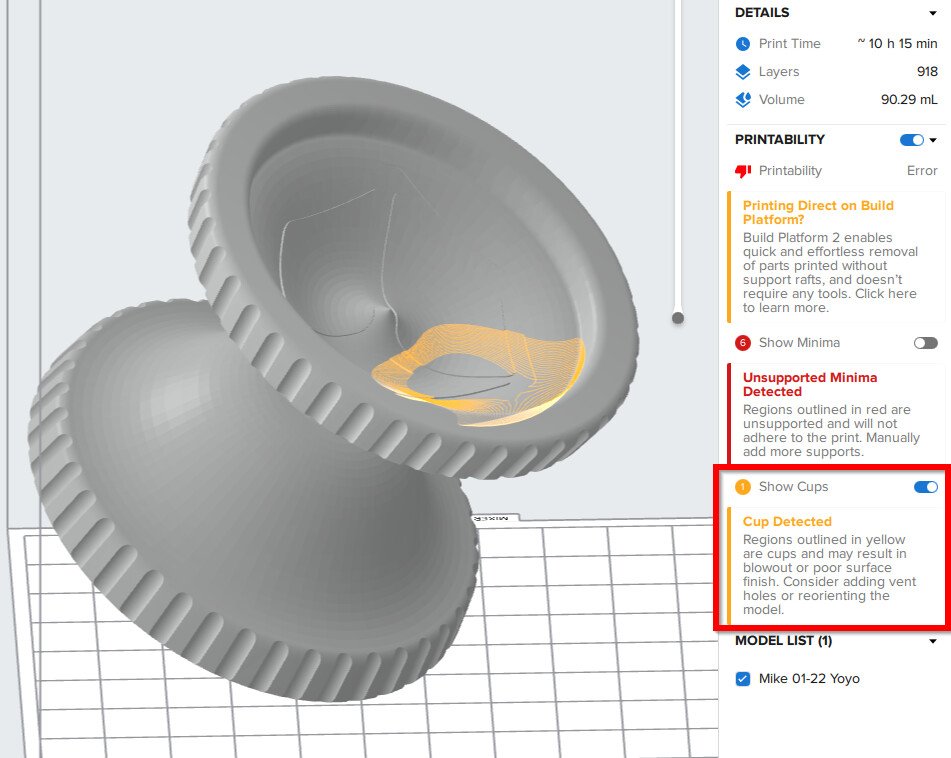
Let’s see what that looks like on the layer view. By manipulating the scroll bar on the right of the graphics area, I can manipulate how my preparation looks at a layer-by-layer basis:

We can see that around layer 536 there are areas that will have no cured resin surrounded completely by areas with cured resin. When the Form 3 is done selectively curing a layer, the build platform is pulled up. When the platform is pulled up in this scenario, this area will create a suction force against the thin plastic film on the bottom of the tray, which could cause it to wear prematurely or even tear the film.
By rotating the model about another axis, I am able to remove that problematic area:

Supports
Supports are necessary for nearly all prints, as described in the Formlabs document above. But what makes a good support? We’ll go through the dialog box:
When creating your own supports, ensure that you do it AFTER your model is tilted for good print performance and after you’ve selected your material.
A feature which differentiates industrial additive manufacturing ecosystems from hobbyist ones is that the features included are very tightly tuned and well-designed. The Preform supports are no exception. If you are going to customize your supports, automatically generate supports first and edit from there.
This is in direct contravention to the conventional wisdom about slicers like CHITUBOX or even PrusaSlicer for the SL-1. Preform is a completely different beast and its algorithm for detecting islands and minima is extremely good.
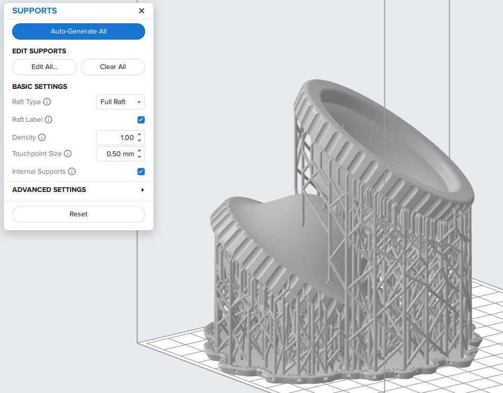
With that knowledge under our belt, hit the “Auto-Generate All” button first. These settings are for Tough 1500 resin, so your defaults may vary. Make sure you keep the “Full Raft” type of support. The material saved is not worth the hassle of working with mini rafts.

The automatically generated supports for this (troublesome) model come out like so:
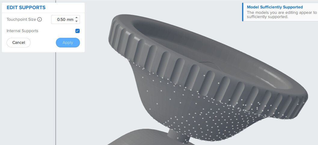
Support Touchpoints
When you hit the “Edit All” button on the supports dialog, you can see that each support is represented by a sphere which intersects the model. That is exactly how they work:
Recall that the volume of a sphere is represented by the following equation:
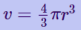
If we want to change the diameter of our touchpoint from 0.5mm to 0.25mm, the strength of the support isn’t halved, but it is less even than the cube root of the original support. The inverse is also true - increasing the size of a support touchpoint dramatically increases the strength of the support in that position.
What this boils down to is you cannot replace one strong support with many weaker ones.
The optimal strategy is to either design your model or find a place in the model you are using where you can hide a large supports and use finer supports throughout. You can also find a balancing act between touchpoint size and density.
Formlabs provide additional information on advanced support settings on this page.
Post Processing
When your model is complete the process goes:
Rinse > Remove Supports > Rinse > Wash > Cure (post curing is optional; not every material requires it).
Support removal is quite easy for an uncured part, keep in mind however the PS1 Paid Parts Program does not remove supports. If your needs are quite particular, reach out to the Industrial CNC Area Host or Form 3 Volunteer Authorizer to work on the particulars of your project.
Depending on the resin chosen, many Form 3 parts can be sanded, media blasted, filled, primed, painted, and machined.
Conclusion:
As stated in the introduction, the automatic settings are sufficient for the vast majority of jobs you’ll want to use on the Form 3. If you are having a challenging time getting the job quite how you need, consider redesigning your model for this manufacturing process or breaking up a downloaded model into multiple components so that supports can be hidden.
Design for Manufacturing Guidelines:
- Supports will leave pockmarks, some large some small; it depends on placement and touchpoint size.
- Have areas where you can “hide” larger supports so they can either be filed down with a needle file or on flat areas which can be lapped against sandpaper on a flat surface.
- Be aware of cavities where resin can get trapped and may be hard to evacuate during rinsing and washing.
- Be careful about feature aspect ratio and minimum feature sizes - more viscous resins such as the Tough 1500 requires at least 1mm gaps between parts, or else the resin will not come loose during rinsing and washing. If liquid resin cannot be evacuated from parts, it will cause them to fuse together.
- Organic shapes may be difficult to avoid having support marks - consider splitting models like these for assembly later.